Data Acquisition in .NET Micro Framework 2.0 using SPI
I mentioned in my earlier post that as part of my last semester at Arizona State University, I was required to create a working demonstration of a product concept for one of my classes. The prototype project required a data acquisition system in a small package, and a display for outputting results. Luckily, I found about the .NET Micro Framework after searching for embedded systems that could be programmed using C#.
The i.MXS Development Kit for SideShow hardware was provided by Freescale. Unfortunately, the development kit was mainly meant for SideShow, as the name suggests so there were some board modifications necessary to make use of the SPI. The unit that I received is version 1.3A (MXSDVK), and one of the differences that can be noticed in this version is the header pins are on the LCD-side of the board.
Before moving on, I should mention that I’m not an expert at this, and the past few months have been a learning period for me. Before this project, I didn’t know how to solder, and had very limited knowledge about circuits. There may be better ways of doing things than how they are presented here.
Also, I would recommend looking through the files in the SDK on the CD included in the box or from the Freescale website.
Modifying the i.MXS Board for SPI
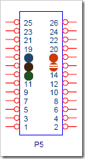
The board had a few missing 0Ω resistors, and had to be addressed. Figure 1 was obtained from the schematics included in the CD (iMXS_Devboard_VER1.3.pdf) on page 7. For our purpose, we bridged the contacts meant for the missing resistors (R60, R61) to connect MISO to header pin 15 and SPI_RDY to pin 17. You can do this using small pieces of wire, and can be seen in Figure 2.
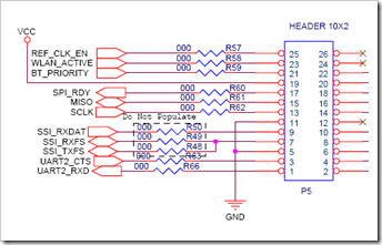
Figure 1: Board Schematic for P5
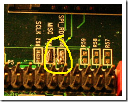
Figure 2: Hardware Modifications
Building the Data Acquisition Circuit
The data acquisition circuit is essentially a voltmeter, and can be connected to different kinds of sensors using a Wheatstone bridge. For the class project, a strain gauge was used to monitor deflections on a small cantilever beam, and an operational amplifier IC was also used to improve the faint signal. Details about those have been omitted for this general guide.
Just a word of caution: this wasn’t meant to be a very precise and accurate system. It worked for my purpose of proving a concept, and might work for other projects as well. The analog-to-digital (AD) converter used for this project is the TLC1549 from Texas Instruments, and will be used to read voltage ranging 0 to 1.8V. This is adequate since most sensors will output a voltage within the range of only a few millivolts (mV).
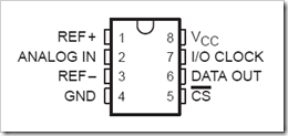
The TLC1549 IC’s pin assignments are shown in the figure below.
Figure 3: TLC1549 Integrated Circuit Pin Assignments
According to the specifications of the TLC1549, the 1.8V pin-out of the i.MXS is within the voltage tolerance of the chip and can be used to power it (VCC). It is also used for the reference voltage (REF+). The lower reference voltage (REF-) is also set to 0V or GND.
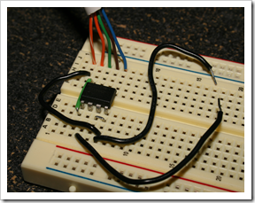
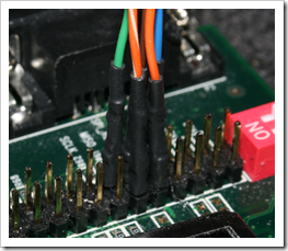
Five wires are needed to connect the TLC1549 to the i.MXS board. I used a scrap piece of CAT5 cable for the wiring, and attached some header pin crimps and some shrink wrap for easy connections. Table 1 summarizes the connections made between the TLC1549 on a breadboard and the i.MXS P5 header row.
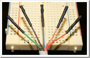
Figure 4: Crimped Wiring and Shrink Wrap
Table 1: Summarized Connections
| TLC1549 Pin | Wiring | i.MXS Board Pin on P5 |
| I/O CLOCK (Pin 7) | Green | SCLK (Pin 13) |
| DATA OUT (Pin 6) | Brown | MISO (Pin 15) |
| CS (Pin 5) | Blue | SPI_RDY (Pin 17) |
| GND & REF- (Pin 4 & 3) | Striped Orange | GND (Pin 16) |
| VCC & REF+ (Pin 8 & 1) | Orange | 1_8V (Pin 18) |
The following figures are photos of the breadboard and the connections between the i.MXS and TLC1549. Open wires were connected to the ANALOG IN (Pin 2) and GND (Pin 4) of the IC. For demonstration, they can be used as probes. Pin 8 and Pin 1 are connected, and Pin 3 and 4 are also connected.
For the sake of simplicity, I have used the SPI_RDY pin of the i.MXS as the chip select (CS) since it will not be used by the TLC1549 chip. Other GPIO pins could have been used, but the SPI_RDY was closer to the other pins being used.
C# Code: Acquiring Data
The real challenge of all this is getting data from the TLC1549 using C#, albeit, it is simple compared to other analog-to-digital chips. Believe me, this can get much more complicated. Below is the DACTLC1549 class highlighting AcquireData() where all the magic happens.
The TLC1549 is a 10-bit AD converter, and for the data acquisition the code uses a ushort data buffer, which is 2 bytes or 16 bits. That means, for every acquisition, the data has to be right-shifted 6 bits as shown in line 31 for proper conversion.
To convert bits to actual voltage readings, a multiplier of (1.8/1023) is used on each reading. The 1.8 comes from the 1.8V being used for reference (REF+). The 1023 comes from the fact that TLC1549 uses 10 bits or 2^10 or 1024 distinct values or 0 to 1023.
I’ve setup the code to acquire multiple samples and display an average of the results because I found that the TLC1549’s initial readings can be a little off. In this case, I used 100 samples.
 1 class DACTLC1549
 2 {
 3   private SPI dacADCSPI;
 4   public DACTLC1549()
 5   {
 6       this.dacADCSPI = new SPI(
 7       new SPI.Configuration(
 8       (Cpu.Pin)77,
 9       false,
10       0,
11       0,
12       false,
13       false,
14       1,
15       Microsoft.SPOT.Hardware.FreescaleMXSDemo.SPI_module.SPI1));
16   }
17   public double[] AcquireData(int samples)
18   {
19       ushort[] databuffer = new ushort[samples];
20       for (int i = 0; i < databuffer.Length; i++)
21       {
22       ushort[] datapoint = new ushort[1];
23       this.dacADCSPI.WriteRead(new ushort[] { 0x00 }, datapoint);
24       databuffer[i] = datapoint[0];
25       Thread.Sleep(1);
26       }
27       double[] data = new double[databuffer.Length];
28       double coeff = (1.8 / 1023.0);
29       for (int i = 0; i < databuffer.Length; i++)
30       {
31       data[i] = (databuffer[i] >> 6) *coeff;
32       Debug.Print((data[i]).ToString());
33       }
34       return data;
35   }
36   public double Average(double[]  signal)
37   {
38       double sum = 0;
39       for (int j = 0; j < signal.Length; j++)
40       {
41       sum = sum + signal[j];
42       }
43       return sum / (double)signal.Length;
44   }
45 }
Results
How does it perform? Here’s a series of tests that can be done to see how it does.
The ANALOG IN probe is attached to GND. Reading: 0.007V. This should be 0V, but it’s very close.
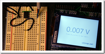
The ANALOG IN probe is attached to VCC. Reading: 1.800V. Dead on.
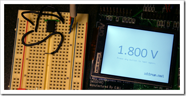
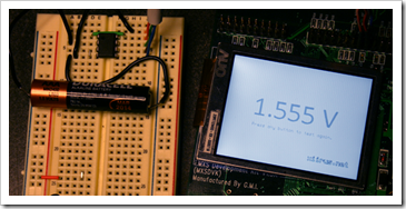
The ANALOG IN probe is attached to the positive side of 1.5V battery and the GND probe on the negative side. Reading: 1.555V.
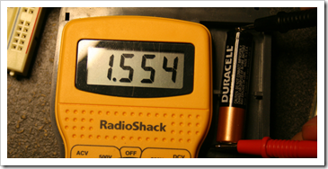
Using a voltmeter, we can verify the reading, and it reads 1.554V for the same battery. It’s a little off, but close enough.
Conclusion
Here we saw how a simple analog-to-digital converter can be used in conjunction with the .NET Micro Framework. I hope this provides a platform for others out there trying to get data acquisition working using the .NET Micro Framework.
If you liked this guide, you might be interested in sharing or linking to this post.
Thanks for dropping by!
Attachment: Source Code
Tags: .NET, .NET Micro Framework, Analog-to-Digital, C#, Code, Data Acquisition, DIY, Electronics, Embedded, Freescale, How To, i.MXS, Microcontrollers, Microsoft, Programming, SPI, Texas Instruments, TLC1549, Visual Studio 2005
Related Posts
Comments

